
Tiny VGA controller
Download tiny-vga.rgate and open it with File → Open…. Registers, adders, and gates generate the raster timing; a pattern ROM supplies RGB444 pixels for the visual display.
Run
- Start simulation with RESET_N=0 and let initialization propagate.
- Click RESET_N to 1, or use Release reset in the display dialog.
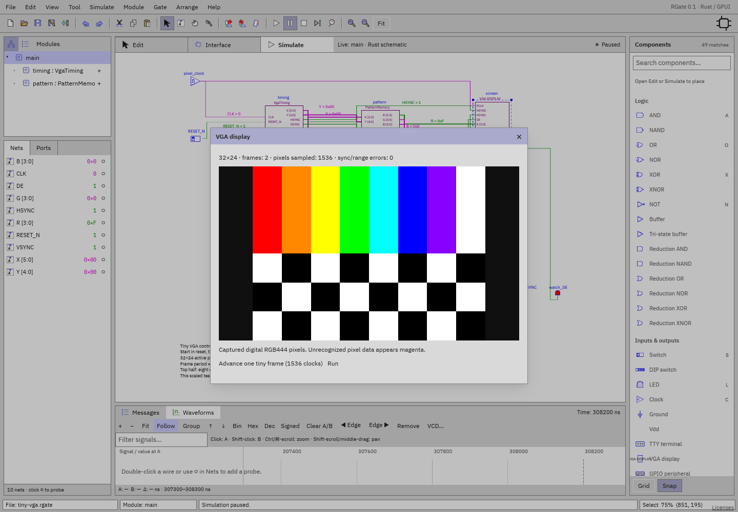
- Double-click screen during simulation.
- Click Advance one tiny frame (1536 clocks) twice to fill and synchronize the frame quickly, or Run. Play is deliberately slow enough to inspect individual cycles.
- The upper half shows eight colored bars; lower half is a black/white checkerboard. Counter/status signals can be probed and inspected live inside the modules.
Timing
| Axis | Active | Front porch | Sync | Back porch | Total |
|---|---|---|---|---|---|
| Horizontal | 32 pixels | 4 | 4 | 8 | 48 pixel clocks |
| Vertical | 24 lines | 2 | 2 | 4 | 32 lines |
Pixel clock period is 100 ns. HSYNC is active-low at X=36–39; VSYNC at Y=26–27. DE is high only in the active rectangle and out of reset. One frame takes 153600 ns, with 768 active pixels. The small raster makes timing and individual pixels easy to inspect in RGate.
Modules
VgaTiming: horizontal register counts modulo 48 using end-line detection and a mux; vertical register increments at line end and naturally wraps modulo 32. Gates decode active area, sync windows, and reset masking.PatternMemory: low five X bits and five Y bits form a 10-bit ROM address. A 1024×12 ROM supplies RGB444; taps expose R/G/B nibbles.main: clock/reset, timing and pattern instances, observing VGA display, and LEDs.
The top color bars are red, orange, yellow, green, cyan, blue, violet, and
white. ROM initialization is editable in PatternMemory; runtime edits are
volatile. Blank-area words are irrelevant while DE=0. The sink samples rising
pixel edges after circuit signals settle and tracks line/frame boundaries
through active-low sync transitions. Unknown color data appears magenta;
sync/range errors are counted.