
LC-3 CPU circuit walkthrough
Examples · Simulation · TTY
Download lc3.rgate and open it with File → Open….
For a second implementation with HDL base modules, see LC-3 with HDL modules.
Explore the computer
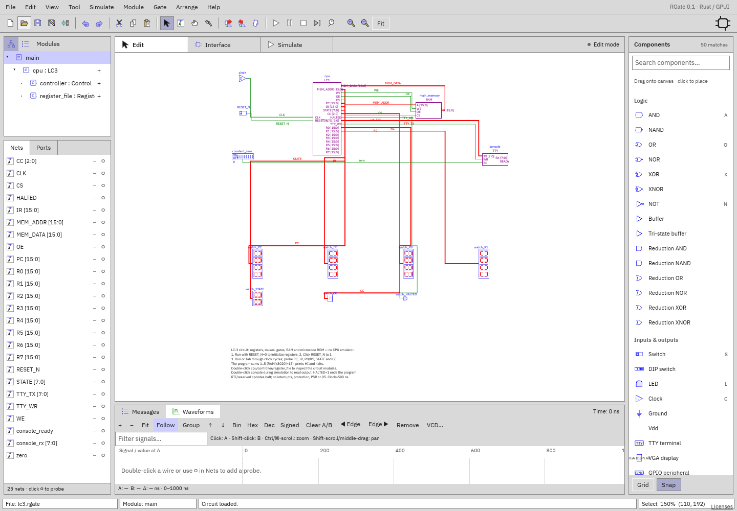
The computer uses a microcoded control circuit, registers, multiplexers, logic gates, and memory. Open its modules to follow instruction execution.
| Definition | Contents |
|---|---|
| main | 500 ns clock, RESET_N switch, 64K×16 logical RAM, TTY, PC/IR/register/status LEDs |
| LC3 | PC/IR/MAR/MDR/CC registers, ADD/AND/NOT datapath, operand muxes, sign extension, memory bus driver, TTY display-address decode |
| RegisterFile | Eight 16-bit registers, one write decoder, two eight-way read muxes |
| Control | Microstate register, opcode dispatch logic, editable 256×32 control ROM |
Use Fit for the whole-computer overview, then zoom into modules to inspect the data path. Junction dots identify connected wires.
Run the included program
- Start simulation with RESET_N=0. Let reset propagate; this clears the registers.
- Click RESET_N to 1. It is active-low: leaving it at 0 holds the CPU in reset indefinitely, even though the clock/time advance.
- Run with Play/Space, or Tab through 500 ns clock periods.
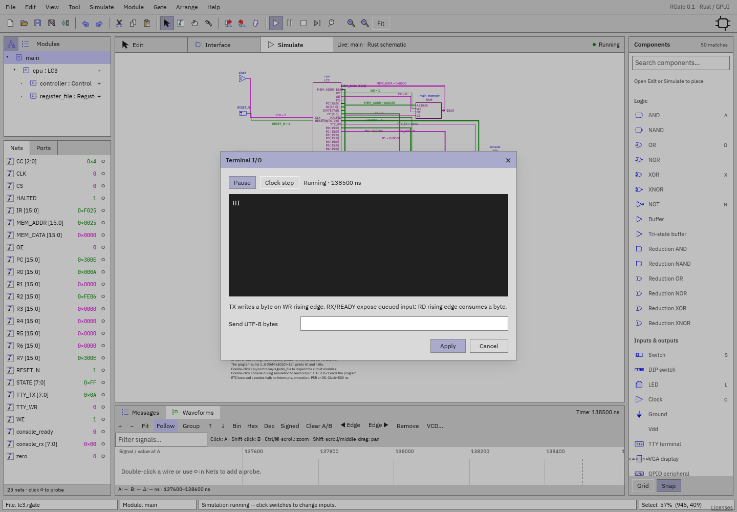
- Double-click
consolewhile simulating. The terminal stays live. If the reset warning appears, click Release reset (RESET_N → 1), then Run. - The output becomes
HIfollowed by a newline. HALTED=1means the program reached HALT. The simulator clock may keep running; the CPU's microstate stays halted.- Double-click
main_memoryand inspect decimal address 12320, which is hex x3020. Its value is 0x000F (15).
Program
The included program clears R0/R1, loads count 5, sums down to 1, stores the result at x3020, loads H/I/newline characters, calls TRAP x21, then TRAP x25.
- lc3-program.asm contains the assembly source.
- lc3-program.hex contains the RAM image.
- TRAP x21 reads a vector at x0021 and runs ordinary LC-3 code at x3100.
- The minimal OUT handler writes to xFE06; the circuit decodes that store to strobe the TTY. It deliberately clobbers R2.
- TRAP x25 halts through the control-ROM path.
Inspect a running CPU
Probe PC, IR, STATE, CC, and R0/R1; then enter main/cpu/controller or
main/cpu/register_file in Tree. Those are live instances of the root run.
Run/pause/step preserve time and state. Use ↑ Parent to return. Child-port
probes can alias root signals; internal probes carry full hierarchical labels.
STATE identifies the current microstate. Fetch and execute span several clock cycles; use clock-step to follow them. VCD can export retained traces for external viewing.
Load or modify a program
Stop simulation, open RAM Properties, and load/edit a hex image. Save an edited copy of the document. Fresh simulation reloads initial RAM; runtime inspector modifications are volatile. RESET_N must be exercised again. Microcode lives in the Control module's ROM and is also ordinary editable configuration.
Instructions to explore
The circuit executes BR, ADD, AND, NOT, LD/ST, LDR/STR, LDI/STI, LEA, JSR/JSRR, JMP/RET, and TRAP vector indirection. Try a branch, a subroutine, or an indirect load/store and follow PC, IR, registers, and memory in the live hierarchy. The control ROM is editable in the Control module.