
Welcome to RGate
A place to build, explore, and understand digital circuits. RGate is a spiritual successor to TkGate, carrying on the tradition of hands-on, open-source circuit design.
Draw a schematic, connect some gates, and see what happens. From your first AND gate to a working computer, there's plenty to explore.
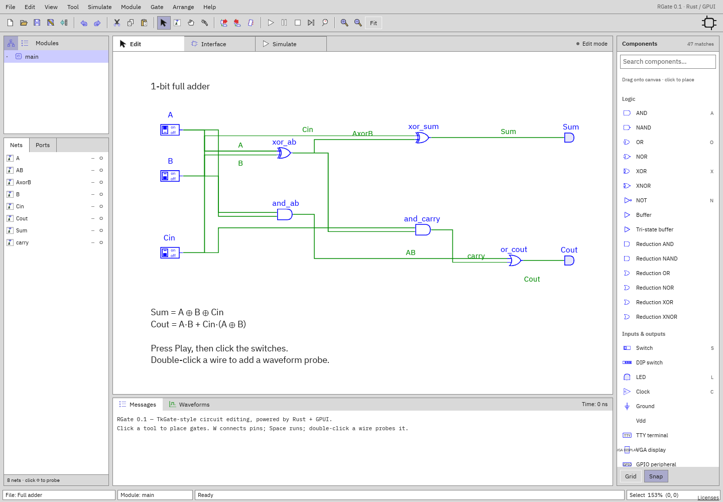
What can it do?
- Draw circuits. Wire up logic gates, switches, memories, and displays.
- Watch them run. Change inputs, step through simulation, and inspect signals.
- Build bigger things. Turn circuits into reusable modules with custom symbols.
- Explore timing. Record signals and read them in the waveform viewer.
- Mix in Verilog. Write HDL modules and connect them to schematics in the desktop app.
Take a look around
- Your first circuit — start with switches and an AND gate.
- The component catalog — gates, buses, memory, and more.
- Example circuits — small experiments and bigger builds.
- An LC-3 computer — look inside a complete little machine.
- A VGA controller — make pixels from digital logic.
- The user manual — get to know the workspace.
A familiar idea, a fresh start. TkGate made digital logic something you could see and experiment with. RGate carries that spirit forward with schematic editing, live simulation, and a browser-based workspace. It's free software, licensed under the GNU GPL v3. Bug reports and contributions are welcome.
Using the manual
The documentation index lists the guides and component reference. Start with simulation, modules and symbols, or waveforms when you're ready to go further. There are also keyboard shortcuts and a troubleshooting page.
Pin directions are relative to the component: an input receives a signal, an output drives one, and an inout does both. Bit 0 is the least-significant bit. Bus widths range from 1 to 4096 bits.
Simulation time is measured in nanoseconds. Active-low controls are asserted
at 0; a rising edge is a transition from 0 to 1. Signals can also be
unknown (X) or floating (Z). Each component page explains its controls and
shows how to use them.