
Routing and bus components
Component index · Editing wires
Multiplexer
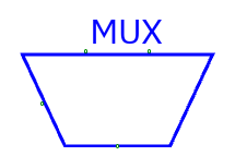
Pins: I0 … I<n−1> data inputs, S select input, Z data output. Data
inputs/output share the configured width. Configure input count (2 or more)
before wiring. Select width is the binary width required for the count, at least
one bit: two inputs → 1 select bit; eight → 3 bits.
S=0 selects I0, S=1 selects I1, etc. Unknown/out-of-range select yields X. A mux chooses a whole data bus. Default is two one-bit inputs.
Example: I0=0x12, I1=0x34, S=1, width=8 → Z=0x34.
Decoder
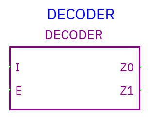
Pins: I binary index input, E scalar enable input, Z0 … Z<n−1>
scalar outputs. Configure 2–64 output count. I width is
ceiling(log2(count)).
E is active-high and unconnected E defaults enabled. When enabled, exactly the output indexed by I is 1; others are 0. E=0 makes all outputs 0. Unknown index/enable yields unknown outputs; a known out-of-range index selects none.
The decoder converts a binary selection to one-hot outputs. Build instruction decoding from taps, decoders, and gates or a ROM.
Demultiplexer
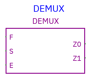
Pins: F data bus, S binary select, E scalar enable, Z0 … Z<n−1>
output buses. Configure output count 2–64 and data width.
With E=1, selected Z receives F; all other Z outputs are zero. E=0 makes all outputs zero. Unknown select/control yields unknowns. Default unconnected E is enabled. Unlike a mux, it sends one input to one of many outputs.
Concatenation (Concat)
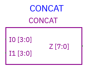
Pins: partition inputs I0 …, full bus output Z. Set Partitions (LSB
first) to comma-separated widths. Each width is positive; the sum must equal
the overall bus width. Up to 64 partitions are supported.
Overall width: 8
Partitions:    4,4
I0 = 0xB (low nibble)
I1 = 0xA (high nibble)
Z  = 0xAB
I0 is the least-significant partition, the reverse of left-to-right Verilog
concatenation notation. The equivalent Verilog expression is {I1, I0}. X/Z
bits are preserved.
Bus splitter
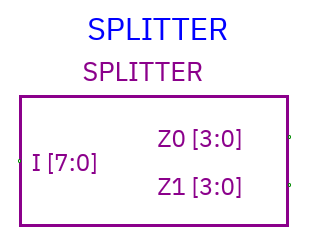
Pins: full bus I, partitions Z0 …. The same partition rules apply. Z0
extracts the low partition, then Z1 the next group of bits.
I=0xAB on eight bits, partitions 4,4 → Z0=0xB, Z1=0xA. Change partitions before wiring; existing net widths won't automatically resize.
Bus tap
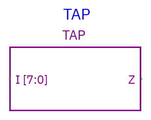
Pins: full bus input I, slice output Z. Configure input width, Tap bit
offset (zero-based LSB index), and Tap output width. Keep the selected
slice within the input bus.
Example: eight-bit I=0xAB, offset=4, output width=4 → Z=0xA. X/Z bits are copied as-is. Tap copies the selected input bits to its output.
You can place Tap explicitly or create one by starting a narrower wire and dropping it onto an existing wider bus. The automatic tap begins at offset 0; use Properties to choose the desired slice. Undo removes the whole automatic-tap edit.
Avoid common width mistakes
Set the source and destination widths before connecting. Choose binary select width separately from data width. A 16-bit mux may have a 1-bit selector; a splitter's 4-bit outputs fit four-bit displays. Use Concat/Tap or matching widths to connect other bus sizes.
Junction dots identify connected wires. Use tri-state enables to coordinate shared-bus drivers, and Concat/Splitter to organize their bit layouts.